(Nanowerk News) At Karlsruhe Institute of Technology (KIT), researchers have developed a flexible and efficient concept to combine optical components in compact systems. They use a high-resolution 3D printing process to produce tiny beam-shaping elements directly on optical microchips or fibers and, hence, enable low-loss coupling. This approach replaces complicated positioning processes that represent a high obstacle to many applications today. The scientists present their concept in the Nature Photonics journal ("In situ 3D nanoprinting of free-form coupling elements for hybrid photonic integration"). | |
In view of constantly growing data traffic, communication with light is gaining importance. For many years now, computing centers and worldwide telecommunication networks have been using optical connections for the quick and energy-efficient transmission of large amounts of data. The present challenge in photonics is to miniaturize components and to assemble them in compact and high-performance integrated systems suited for a variety of applications, from information and communication technologies to measurement and sensor technologies, to medical engineering. | |
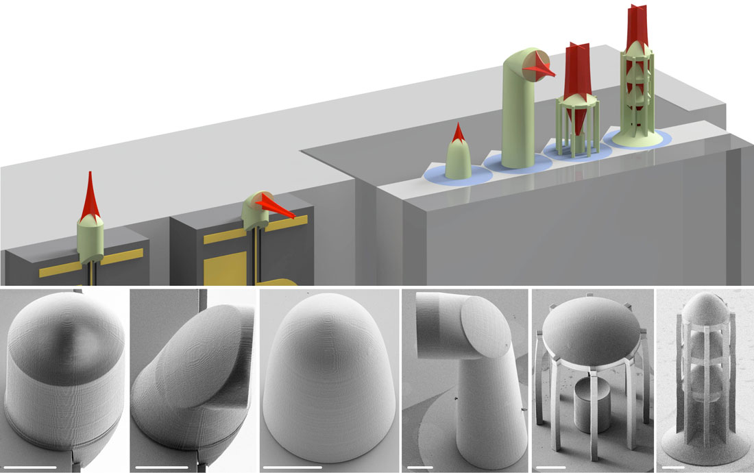
Microlenses and micromirrors can be produced on optical fibers and microchips by 3D nanoprinting. This considerably facilitates assembly of photonic systems. (Image: Philipp-Immanuel Dietrich/Florian Rupp/Paul Abaffy, Karlsruhe Institute of Technology) (click on image to enlarge) | |
In this respect, hybrid systems are of very high interest. They combine a number of optical components with different functions. Hybrid systems offer superior performance and design freedom compared to monolithic integration concepts, for which all components are realized on a chip. Hybrid integration, for instance, allows individual optimization and testing of all components before they are assembled to a more complex system. Setup of optical hybrid systems, however, requires complex and expensive methods for the highly precise alignment of components and low-loss coupling of optical interfaces. | |
Researchers of KIT have how developed a new solution for the coupling of optical microchips to each other or to optical fibers. They use tiny beam-shaping elements that are printed directly onto the facets of optical components by a high-precision 3D printing process. These elements can be produced with nearly any three-dimensional shape and enable low-loss coupling of various optical components with a high positioning tolerance. | |
The researchers validated their concept in several experiments. They produced micrometer-sized beam-shaping elements of various designs and tested them on a variety of chip and fiber facets. As reported by the scientists in the journal Nature Photonics, they reached coupling efficiencies of up to 88% between an indium phosphide laser and an optical fiber. The experiments were carried out at the Institute of Microstructure Technology (IMT), the Institute of Photonics and Quantum Electronics (IPQ), and the Institute for Automation and Applied Informatics (IAI) of KIT, in cooperation with the Fraunhofer Institute for Telecommunications (Heinrich Hertz Institute, HHI) in Berlin and IBM Research in Zurich. The technology is presently being transferred to industrial application by Vanguard Photonics, a spinoff of KIT, under the PRIMA project funded by the Federal Ministry of Education and Research. | |
For the production of the three-dimensional elements, the researchers used multi-photon lithography: Layer by layer, a laser with an ultrashort pulse length writes the given structures into a photoresist that hardens simultaneously. In this way, 3D structures as small as a few hundred nanometers can be printed. Apart from microlenses, the process is also suited for producing other free-form elements, such as micromirrors, for the simultaneous adaptation of beam shape and propagation direction. In addition, complete multi-lens systems for beam expansion can be fabricated. With them, positioning tolerance during assembly of the components is enhanced. | |
“Our concept paves the way to automated and, hence, cost-efficient manufacture of high-performance and versatile optical hybrid systems,” says Professor Christian Koos, Head of IPQ and member of the Board of Directors of IMT as well as co-founder of Vanguard Photonics. “Hence, it essentially contributes to using the vast potential of integrated optics in industrial applications.” |
A repository & source of cutting edge news about emerging terahertz technology, it's commercialization & innovations in THz devices, quality & process control, medical diagnostics, security, astronomy, communications, applications in graphene, metamaterials, CMOS, compressive sensing, 3d printing, and the Internet of Nanothings. NOTHING POSTED IS INVESTMENT ADVICE! REPOSTED COPYRIGHT IS FOR EDUCATIONAL USE.
Showing posts with label IBM. Show all posts
Monday, April 23, 2018
3D Nanoprinting facilitates communication with light
https://www.nanowerk.com/nanotechnology-news/newsid=49995.php
Wednesday, April 8, 2015
OT-Silicon photonics a step closer to enabling faster, cheaper and lower energy computing
Scientists at IBM Research have demonstrated what may be an important step towards future applications in the field of cloud-computing, big data, analytics and cognitive computing. The team established a method to integrate silicon photonic chips with the processor in the same package, avoiding the need for transceiver assemblies.
The new technique, which was presented 25 March at this year's OFC Conference and Exposition in Los Angeles, California, USA, could lower the cost and increase the performance, energy efficiency and size of future data centres, supercomputers and cloud systems.
Photonic devices offer many advantages compared to traditional electronic links found in today’s computers, as optical links can transmit more information over larger distances and are more energy efficient than copper-based links.
To benefit from this technology, a tight integration of the electrical logic and optical transmission functions is required. The optical chip needs to be as close to the electrical chip as possible to minimise the distance of electrical connection between them; however, this can only be accomplished if they are packaged together.
Optical interconnect technology is currently incorporated into data centres by attaching discrete transceivers or active optical cables, which come in pre-assembled building blocks. The pre-packaged transceivers are large and expensive, limiting their large-scale use. Furthermore, such transceivers are mounted at the edge of the board, resulting in a large distance between the processor chip and the optical components.
IBM researchers from Europe, the United States and Japan instead proposed an integration scheme in which the silicon photonic chips are treated similarly to ordinary silicon processor chips and are directly attached to the processor package without pre-assembling them into standard transceiver housings. This improves the performance and power efficiency of the optical interconnects while reducing the cost of assembly.
The team demonstrated efficient optical coupling of an array of silicon waveguides to a substrate containing an array of polymer waveguides.
Challenges arise because alignment tolerances in photonics are critical (sub-micron range) and optical interfaces are sensitive to debris and imperfections. Another challenge arose from the significant size difference between the silicon waveguides and the polymer waveguides originally presented. The researchers overcame this obstacle by gradually tapering the silicon waveguide, leading to an efficient transfer of the optical signal to the polymer waveguide.
The method is scalable and enables the simultaneous interfacing of many optical connections between a silicon photonic chip and the system. The optical coupling is also wavelength and polarisation insensitive, and tolerant to alignment offsets of a few micrometres.
'This integration scheme has the potential to massively reduce the cost of applying silicon photonics optical interconnects in computing systems,' said Bert Offrein, manager of the photonics group at IBM Research-Zurich. Cheaper photonic technology enables its deployment at a large scale, which will lead to computing systems that can process more information at higher performance levels and with better energy efficiency, he explained.
'Such systems will be key for future applications in the field of cloud-computing, big data, analytics and cognitive computing. In addition, it will enable novel architectures requiring high communication bandwidth, as for example in disaggregated systems,' Offrein added.
Tuesday, August 19, 2014
IBM assigned Patent for Generation of Terahertz Electromagnetic Waves in Graphene By Coherent Photon-mixing
http://technews.tmcnet.com/news/2014/08/19/7978040.htm
*** International Business Machines Assigned Patent for Generation of Terahertz Electromagnetic Waves in Graphene By Coherent Photon-mixing ALEXANDRIA, Va., Aug. 18 -- International Business Machines, Armonk, New York, has been assigned a patent (8,805,148) developed by four co-inventors for the "generation of terahertz electromagnetic waves in graphene by coherent photon-mixing." The co-inventors are Phaedon Avouris, Yorktown Heights, New York, Chun-Yung Sung, Poughkeepsie, New York, Alberto Valdes Garcia, Hartsdale, New York, and Fengnian Xia, Plainsboro, New Jersey.
The patent application was filed on July 14, 2011 (13/182,621). The full-text of the patent can be found athttp://patft.uspto.gov/netacgi/nph-Parser?Sect1=PTO1&Sect2=HITOFF&d=PALL&p=1&u=%2Fnetahtml%2FPTO%2Fsrchnum.htm&r=1&f=G&l=50&s1=8,805,148.PN.&OS=PN/8,805,148&RS=PN/8,805,148 Written by Balkishan Dalai; edited by Jaya Anand.
Wednesday, February 12, 2014
OT-Turbocharging Channels With Compounds
Feb 11, 2014
http://www.compoundsemiconductor.net/csc/features-details.php?cat=features&id=19737265
Four decades of scaling CMOS technology has revolutionized our society. By making transistors ever smaller, faster, cooler, and cheaper, and being able to pack billions of them on the same chip, engineers have enabled the smartphone to become a commodity. This sleek, portable device has fundamentally changed the way we live: Now, wherever we are, we can be participating members of social networks and surfers of the web.
Performance of the smartphone will continue to increase, but it will not be easy to realise further gains in the computational capability of the chips that lie at the heart of these devices. That’s because the microelectronic industry is facing some really serious challenges in shrinking dimensions beyond the 14 nm node.
Even getting as far as we have today has not been easy. For the last decade, pure geometrical scaling has failed to deliver the expected benefits in terms of performance and power consumption, and industry has gradually moved to innovation-driven scaling, bringing to market chips based on the likes of strained silicon-on-insulator, high-k/metal gate technology and tri-gate devices. Now researchers everywhere are foreseeing that in the coming years, silicon – regardless of its form - will probably fail to meet the ultra-low power consumption targets imposed by the exploding demand of ‘Mobile-Everywhere’ applications.
The main lever for power scaling is the operating voltage of the chips. The target is to trim this from 0.8-0.9 V, which is where it stands today, down to 0.5 V. This cut in operating voltage must go hand-in-hand with a maintaining of the drive-current for the transistors, in order to ensure no reduction in performance. But realising this will not be easy. It will require the charge carriers in the transistor’s channel – either electrons or holes, depending on the particular transistor − to travel far faster from the source to the drain. Today, increases in the charge carrier velocity in silicon often result from the application of very high levels of strain in the material, but the opportunities for further gains are now minimal, especially for n-type transistors.
What is possible is that the next revolution in the semiconductor industry will come from the introduction of compound semiconductors as channel materials. Electron and hole mobilities in silicon are just 1400 cm2 V-1 s-1 and 450 cm2 V-1 s-1, respectively, and far higher values are promised by switching to carefully selected III-V and IV-IV compounds. For example, the electron mobility in InGaAs is in excess of 10,000 cm2 V-1 s-1, while hole mobility in SiGe can hit 1900 cm2 V-1 s-1. Using these materials to form thep-type andn-type transistors for CMOS chips would allow the indium and germanium content in the channels to become a new scaling parameter, gradually increasing the carrier velocity for each new technology node and thus improving performance while lowering power consumption.
Researchers will have to answer many questions before it is possible to build hybrid dual-channel CMOS circuits featuring very-large-scale integration (VLSI). They include: How do you get high-mobility channels on a silicon substrate with a good crystalline quality? How do you build nano-scaled devices based on III-Vs and SiGe that are compatible with VLSI? And how do you co-process both types of devices, given the fundamentally different thermal budgets and chemistries that they require?
A team at the IBM Zurich Research Laboratory in Switzerland has been focusing on finding answers to these questions for the last eight years. Efforts have now paid dividends: They have developed novel engineered substrates and process technologies for high-volume manufacturing in silicon foundries of VLSI circuits with compound semiconductor materials.
Silicon foundations
Although the microelectronic industry will have to undergo some big changes in the coming years, this will not include a change in substrate. So, to enable III-V and IV-IV compounds to be integrated in CMOS production, these materials will have to be introduced on a silicon substrate.
This is not easy, because integration of different, high-quality crystalline materials demands a matching of crystalline arrangement and lattice constant. While InGaAs, germanium and silicon have a similar crystalline arrangement, their lattice constants are significantly different: Compared to silicon, the average atomic spacing is about 4 percent larger for germanium and 8 percent larger for InGaAs. It is possible to manage the lattice mismatch for SiGe and germanium with some engineering tricks, but this is not possible with InGaAs, because the mismatch between this alloy and silicon is far too high. If attempts are made to grow InGaAs directly on silicon, strain in the ternary is so high that this material relaxes by forming an excessively large number of crystalline defects, which would significantly degrade device performance.
Today, to overcome this defect-related weakness, industrial researchers are pursuing two approaches. One of the options is known as aspect ratio trapping, while the other – pioneered at IBM – is called direct wafer bonding (see Figure 1 for an overview).
Figure 1. Comparison of the two main routes to integrate III-V on Si substrates: Aspect ratio trapping (on the left) and direct wafer bonding (on the right)
Aspect ratio trapping exploits the defined angles of the crystalline defects. The starting point is to take a silicon substrate and etch out a narrow trench – that is, one with a high aspect ratio, or in other words a groove with a height that is several times greater than its width. When III-Vs are grown directly in this trench, defects form at the interface and propagate along defined angles, before terminating on the trench walls. Thanks to this defect-elimination process, a low defect InGaAs crystal is created at the top of the trench. However, while this argument is applicable across the trench, where there is a high aspect ratio, it fails to hold true along the trench, where defects can propagate to the top channel material. This means that the channel material sitting on top of the trench is located on top of a defective semiconductor, which creates potential leakage paths from source to drain.
Aspect ratio trapping also restricts the availability of InGaAs. As this ternary is only present above the trenches, circuit designers are restricted in their positioning and sizing of the transistors. However, this issue disappears if the trenches can be tied together at a very small pitch, as required for the silicon fins of today.
Despite all these drawbacks associated with aspect ratio trapping, it still attracts a lot of attention, because it is directly compatible with silicon foundries that are now running 300 mm lines and could upgrade to 450 mm. However, foundries may find it much easier to pursue the technology that IBM is developing: direct wafer bonding.
With this approach, thin layers of III-Vs can be transferred onto silicon in the same manner already employed by industry to build silicon-on-insulator (SOI) substrates. Engineers simply grow the InGaAs layer on a donor substrate, before bonding it via an oxide to a target silicon substrate. The thin III-V layer is then released from the donor wafer to yield a III-V-on-insulator structure on silicon. This approach allows the donor wafer to be recycled, thereby maintaining the cost-efficiency of this process.
There are many attractive attributes associated with having a very thin III-V channel on an insulator. This
combination is an ideal structure for maintaining good electrostatic control of the gate over the channel at short gate lengths, and it efficiently cuts leakage currents from source to drain. What’s more, this combination enables the use of the back-biasing technique, which permits dynamic adjustments of the transistor’s operation, so that it can be tuned to be faster or more power-efficient. All these merits reveal why III-V-on-insulator could be the preferred option for low power applications, such as mobile electronics.
The Zurich researchers have used wafer-bonding to create a hybrid, dual-channel substrate that uses a thin insulator to separate a 6 nm-thick InGaAs film from an 8 nm-thick SiGe layer on a silicon substrate (see Figure 2). This engineered platform has enabled both channel materials to be integrated on the same substrate for the first time, while matching the thickness requirements of the 14 nm technology node. This breakthrough should pave the way towards the production of dual-channel CMOS circuits, where n-type transistors could be built on InGaAs and p-type transistors on SiGe.
Figure 2. Photograph and associated cross-sectional illustration of a high-mobility dual-channel substrate which comprises a 6 nm thick InGaAs layer on a 8 nm thick SiGe layer on a silicon handling substrate
III-V challenges
As readers of this magazine all know, III-V materials have been used for many years for the manufacture of myriad RF/analog chips, LEDs, lasers, solar cells and high-power devices. However, although a lot of know-how has been developed and accumulated over several decades, none of these applications require the fitting of billions of devices onto an area the size of a fingernail – a requirement imposed by CMOS chips. This additional constraint forces engineers and scientists to revolutionize the way III-V devices are fabricated, because gate lengths must be shorter than 20 nm, and, more importantly, contacts have to fit in less than 50 nm.
These pre-requisites cannot be met by turning to different lithography levels to define the different elements of the devices, because transistors are way too small. Instead, a so-called self-aligned process has to be developed that enables the construction of all the different building blocks of the device with a single lithography step: the gate definition. By taking this approach, device dimensions and device pitches can be aggressively scaled to meet the requirements of VLSI integration.
In 2012, the Zurich team showed that it is possible to fabricate self-aligned InGaAs transistors. These VLSI-compatible devices feature a gate-first high-k/metal-gate process with raised source-drain regions, which are just like those employed in industry for the manufacture of the most advanced silicon CMOS technology nodes.
The first ‘bulk’ transistors were fabricated on InP wafers (see Figure 3a), with successful operation down to gate lengths as small as 60 nm. The team then went one better, transferring the fabrication flow to III-V-on-insulator substrates on silicon, which had an InGaAs channel layer just 10 nm-thick (see Figure 3b).
Figure 3. (a) Cross-sectional TEM view of a “bulk” self-aligned InGaAs transistor on InP featuring high-k/metal-gate technology and raised source-drain. (b) Cross-sectional TEM view of an InGaAs transistor fabricated with the same process flow but transferred on a III-V-on-insulator on Si substrate. (c) Comparison of DIBL versus gate length for both types of transistors showing up to a factor of five reduction for devices on insulator
Within the SOI industry, it is well known that this class of engineered substrate offers a large performance boost, thanks to the confinement of the carriers in a very thin channel and better electrostatic integrity. Superior performance translates to a reduction in the drain-induced barrier lowering (DIBL) of the transistors by up to a factor of five (see Figure 3c). DIBL is a key figure-of-merit for the electrostatic performance.
Further accomplishments by IBM Zurich include the construction of InGaAs transistors with a 24 nm gate and a gate-to-gate spacing of just 300 nm (see Figure 4). To date, they represent the smallest, most compact VLSI-compatible InGaAs transistors reported on silicon.
Figure 4 (above). Cross-sectional TEM view of densely packed InGaAs devices on silicon substrates with gate lengths of only 24 nm
Dual channel developments
In addition to building standalone devices, the advanced dual-channel substrate technology can be used as a base for building small CMOS circuits. One of the benefits of this approach is that both channel materials are stacked on top of each other, so are present everywhere on the wafer. After defining some islands where transistors should be, the InGaAs channel can be removed to expose the SiGe channel where p-type devices are to be built (see Figure 5a).
Figure 5. (a) Schematic process flow for the fabrication on hybrid InGaAs/SiGe CMOS circuits based on high-mobility dual-channel substrates. (b) Top-view SEM image on a dense CMOS inverter chain fabricated with 90nm design rules. (c) Hybrid CMOS inverter output characteristic showing a working circuit
Although having both InGaAs and SiGe channels on the same wafer is an enviable starting point, this comes at the penalty of more challenging material processing. InGaAs and SiGe exhibit fundamentally different chemical natures, so processes that work fine with one material can cause etching of the other. To address this, the researchers modified the fabrication flow for building InGaAs transistors on insulator, introducing new chemical cleans, passivation and etch-stop layers.
Thanks to all these developments, the team has have been able to demonstrate the first construction of dense arrays of CMOS inverters built with 90 nm design rules on silicon substrates that feature high-mobility channel materials (see Figure 5b). Inverters are the simplest logic block, and an important step towards the building of more complex CMOS circuits. Thus, by showing an InGaAs/SiGe inverter operating down to 0.2 V (see Figure 5c), the concept of using high mobility materials for CMOS has been validated. What’s more, the door has been opened to further developments that could ultimately enable an up-scaling of the technology for high-volume manufacturing.
Clearly, the next steps are to build more complex CMOS circuits such as ring-oscillators and SRAM cells (a very common memory cell featuring six transistors). Armed with these circuits, the team will be able to assess the speed, performance and maturity of this advanced CMOS technology. However, the key test for this hybrid circuit will be to scale its dimensions to that of a state-of-the-art silicon chip and see how it compares. If it performs well, introduction in the foundries will then hinge on whether there are tough manufacturing issues associated with implementing this process. If these new channels materials make an impact, it will open up a new era for the microelectronic industry, where new functions are integrated into chips. It may not be long, for example, until the time comes when multi-core CMOS chips could communicate between cores with light via integrated III-V lasers, while making use of terahertz frequencies. So the promise of hybrid chips is awesome. However, as yet no one knows quite when – or exactly how – this is going to happen.
Further reading
C. Marchiori et. al.J. Phys. D: Appl. Phys. 47(2014) 055101 (2014)
L. Czornomaz et. al.IEDM Tech. Dig., 2.8, pp. 52-55 (2013)
L. Czornomaz, et. al.43rd IEEE ESSDERC Proceedings, pp. 143-146 (2013)
N. Daix et. al. IEEE S3S Proceedings, in press (2013)
L. Czornomaz et. al.IEDM Tech. Dig., 24.3, pp. 517-520 (2012)
L. Czornomaz et. al.70th IEEE DRC, 207-208 (2012)
M. El. Kazzi et. al.Appl. Phys. Lett. 100063505 (2012)
L. Czornomaz et. al.Solid-State Electronics 7471 (2012)
Tuesday, February 4, 2014
Graphene Circuit Competes Head-to-Head With Silicon Technology
IBM has built on their previous graphene research and developed what is being reported as the best graphene-based integrated circuit (IC) built to date, with 10 000 times better performance than previously reported efforts.
This graphene-based IC serves as a radio frequency receiver that performs signal amplification, filtering and mixing. In tests, the IBM team was able to use the circuit to send text messages (in this case, “IBM”) without any distortion.
“This is the first time that someone has shown graphene devices and circuits to perform modern wireless communication functions comparable to silicon technology,” IBM Research director of physical sciences Supratik Guha said in a release.
The IC, which is fully described in the journal Nature Communications(“Graphene radio frequency receiver integrated circuit”), overcomes major problems previously encountered with graphene-based ICs that cause the transistor performance to degrade.
The key to overcoming this issue was a new manufacturing method. Simply put, the graphene is added late in the process to prevent it from being damaged during other manufacturing steps.
Despite the improved manufacturing method for the IC, the IBM researchers still depended on a costly method for producing the graphene that was used. They believe that if a high-quality graphene could be produced in a roll-to-roll process, the IC would become easier and cheaper to produce.
This latest circuit builds on the first integrated circuit built from graphene—developed by IBM in 2011—that was a broadband radio-frequency mixer, a fundamental component of radios that processes signals by finding the difference between two high-frequency wavelengths.
While others have judged the odds that graphene will yield benefits in electronic applications as slim to none because it lacks an inherent band gap, IBM has stayed on a steady course to test those assumptions. In early 2010, Big Blue researchers engineered a band gap into graphene large enough to pursue the use of graphene in infrared (IR) and terahertz (THz) detectors and emitters. Then a year later, IBM followed up with a graphene transistor capable of operating at 100 gigahertz that has the same gate length as silicon chips with speeds of 40 GHz. Of course, a transistor on its own can’t do much of anything, so about six months later, IBM reported building the first integrated graphene circuit that was the precursor to this latest version.
In describing the impact of the research, Shu-Jen Han of IBM Research said in an IBM blog:
“Our demonstration has the potential to improve today’s wireless devices’ communication speed, and lead the way toward carbon-based electronics device and circuit applications beyond what is possible with today’s silicon chips. Integrating graphene radio frequency (RF) devices into today’s low-cost silicon technology could also be a way to enable pervasive wireless communications allowing such things as smart sensors and RFID tags to send data signals at significant distances.”
With IBM's apparent relentless pursuit of an IC for a radio frequency receiver, it would seem that seeing these devices in our telephones at some point in the future could be a realistic prospect.
Photo: IBM Research - Zurich
Thursday, July 25, 2013
IBM Demonstrates a Competitive Graphene Infrared Detector
Image: Tony Low
In the image, plasmon dispersion in graphene on silicon dioxide substrate, reveals coupling with long-lived substrate phonons. They can be excited by patterning graphene into nanoribbons.
By Dexter Johnson
Posted
Earlier this year, researchers at IBM’s Nanoscale Science and Technology group revealed some of the fundamental photoconductivity mechanisms of graphene.
The IBM researchers demonstrated that graphene can either be positive or negative depending on its gate bias. The positive is due to a photovoltaic effect and the negative is due to a bolometric effect.
The bolometric effect involves photo-generated carriers that, while propagating across graphene, emit quanta of lattice vibrations called phonons and thereby transfer their energy into the lattice. Heating up the lattice implies enhancing the electron-phonon scattering process and reducing the carrier’s mobility. The IBM researchers discovered this effect was dominant in the photo response of graphene and is what leads to the photocurrent flowing in the opposite direction of the source-drain current.
In new research, which was published both in Nature Communications(“Photocurrent in graphene harnessed by tunable intrinsic plasmons”) andNature Photonics (“Damping pathways of mid-infrared plasmons in graphene nanostructures”), the IBM team has begun to explore ways to amplify this bolometric effect in graphene.
The research team, which includes Hugen Yan, Tony Low, Wenjuan Zhu, YanqingWu, Marcus Freitag, Xuesong Li, Francisco Guinea, Phaedon Avouris, and Fengnian Xia, began by first studying the fundamental property of plasmons in graphene metamaterials by purely optical methods, revealing important information about its dispersion and damping mechanisms. This knowledge guided them in their design of graphene photodetectors, leading to the first demonstration of a graphene infrared detector driven by intrinsic plasmons.
Graphene’s high mobility and zero gap nature gives it fast optoelectronic response and detection in an extremely broad spectral range from the visible over the infrared and into the terahertz range.
In the visible and near-IR, semiconductors are more efficient in detecting light than graphene because they can have matched bandgaps to a particular spectral window, and because a single layer of graphene absorbs only a small fraction of the incoming light. So it is very unlikely that we will some day be able to buy a cell-phone or camera with a graphene photodetector in it.
However, at lower energies, for example in the mid-IR or terahertz regime, graphene could be much more competitive and provide a unique technology solution. Currently, superconducting transition-edge detectors and bolometers are state of the art in these regimes, and these detectors are very expensive. The absorption in a single layer of graphene can be as high as 40 percent in the terahertz, and the window of high absorption can be moved into the mid-IR by patterning the graphene and harvesting graphene plasmons.
The graphene-based photodetectors, which utilize their intrinsic plasmons, have been demonstrated to yield an order of magnitude improvement in the device’s photo-responsivity in comparison to its non-plasmonic counterpart.
The graphene used in the photodetectors were first grown by CVD on copper foil. Copper was then dissolved in etchant, and finally graphene was transferred to a silicon/silicon oxide chip. The researchers built the graphene photodetector itself by patterning graphene into superlattices of graphene nanoribbons using e-beam lithography. The ribbons widths range from 80 to 200 nm and lateral confinement in ribbons provides the necessary momentum to couple with the graphene plasmons. It is then illuminated with a chopped CO2 infrared laser beam.
The researchers believe that graphene plasmonics could potentially provide a natural platform for a range of technologies in the infrared regime such as light detection and modulation, optical communications, photovoltaics, and spectroscopy.
With this basic understanding of how graphene plasmon disperses, damps, and generates photocurrent, the IBM team is now more confident about this line of research. The merging of graphene plasmonics with optoelectronics is a field that has essentially just began so there remain fundamental and technological issues to resolve.
Tuesday, March 5, 2013
Researchers at Georgia Tech develop terabit wireless antennas
by Gareth Halfacree
http://www.bit-tech.net/news/hardware/2013/03/05/georgia-terabit/1
Researchers at the Georgia Institute of Technology have designed a graphene-based antenna that could potentially allow for data transfer rates as high as a terabit per second over a metre range.
The system, developed by a team from the Broadband Wireless Networking Laboratory at Georgia Tech led by director Ian Akyildiz, uses graphene - sheets of carbon just one atom thick arrayed in a honeycomb structure - to create narrow strips between 10 and 100 nanometres wide and one micrometer long, forming terahertz frequency antennas. Electrons oscillating on the surface of each graphene strip, known as plasmonic waves, interact with electromagnetic waves at the terahertz frequency in order to receive or transmit a signal.
According to the team's calculations, such a terahertz radio system could transfer data at a rate of one terabit per second - roughly 2,330 times faster than 802.11n Wi-Fi. While that is only sustainable at a range of a metre or less, as a close-range data-transfer tool the team's graphene-based antenna could prove extremely useful indeed: drop the range to a handful of centimetres and the data transfer
Such a system could be a boon for external peripherals that rely on the transfer of large quantities of data. A high-definition video camera, for example, could dump all its footage in under a second just by being placed near a laptop or desktop equipped with the team's antenna, or a smartphone quickly download rented or purchased films for on-the-go viewing.
Sadly, as is often the case with such 'breakthroughs' involving the wonder-material graphene, the technology is far from a commercial reality just yet. '[The team's work] points out and provides a set of classical calculations on estimates of sizes and performance: it points out that there is something worthwhile here' explained Phaedon Avouris, IBM research fellow and graphene expert, in an interview on the subject with MIT Technology Review. It doesn’t solve the whole problem, but points out an opportunity.'
The team's work, which has up to this point been purely theoretical, will need proving with a prototype device - something Akyildiz claims is due for unveiling before the end of the year - and then the antenna will need to be mated to other high-performance hardware in order to reach anywhere near the terabit speeds promised. However, with the research
Wednesday, December 26, 2012
Slightly OT- IBM announces breakthrough in silicon nanophotoncs
My Note: This has nothing directly to do with Terahertz but portends a number of developments that will occur "across the board" in technology, with advances in silcon nanophotonics.
On December 10, 2012 IBM announced a breakthrough optical communication technology which has been verified in a manufacturing environment. The technology – called “silicon nanophotonics” – uses light instead of electrical signals to transfer information for future computing systems, thus allowing large volumes of data to be moved fast between computer chips in servers, large data-centers, and supercomputers via pulses of light.
The technology breakthrough allows the integration of different optical components side-by-side with electrical circuits on a single silicon chip, for the first time, in standard 90nm semiconductor fabrication. The new features of the technology include a variety of silicon nanophotonics components, such as modulators, germanium photodetectors and ultra-compact wavelength-division multiplexers to be integrated with high-performance analog and digital CMOS circuitry.
The use of a standard chip manufacturing process will alleviate high cost of traditional interconnects. Single-chip optical communications transceivers can now be manufactured in a standard CMOS foundry, rather than assembled from multiple parts made with expensive compound semiconductor technology.
Furthermore, dense integration of optical circuits capable of transmitting and receiving at high data rates will solve the limitations of congested data traffic in current interconnects. IBM’s CMOS nanophotonics technology demonstrates transceivers to exceed the 25Gbps data rate. In addition, the technology is capable of feeding a number of parallel optical data streams into a single fiber by utilizing compact on-chip wavelength-division multiplexing devices. The ability to multiplex large data streams at high data rates will allow future scaling of optical communications capable of delivering terabytes of data between distant parts of computer systems.
In summary:
Cross-sectional view of an IBM Silicon Nanophotonics chip combining optical and electrical circuits
An IBM 90nm Silicon Integrated Nanophotonics technology is capable of integrating a photodetector (red feature on the left side of the cube) and modulator (blue feature on the right side of the cube) fabricated side-by-side with silicon transistors ( red sparks on the far right of the cube). Silicon Nanophotonics circuits and silicon transistors are interconnected with nine levels of yellow metal wires.
Information super highways inside an IBM Silicon Nanophotonics chip.
Angled view of a portion of an IBM chip showing blue optical waveguides transmitting high-speed optical signals and yellow copper wires carrying high-speed electrical signals. IBM Silicon Nanophotonics technology is capable of integrating optical and electrical circuits side-by-side on the same chip.
Monday, December 10, 2012
Engineers make tiny, low-cost, terahertz imager chip
The new terahertz chips developed by Caltech electrical engineers, shown with a penny for scale. Credit: Kaushik Sengupta/Caltec
http://phys.org/news/2012-12-tiny-low-cost-terahertz-imager-chip.html#jCp
(Phys.org)—A secret agent is racing against time. He knows a bomb is nearby. He rounds a corner, spots a pile of suspicious boxes in the alleyway, and pulls out his cell phone. As he scans it over the packages, their contents appear onscreen. In the nick of time, his handy smartphone application reveals an explosive device, and the agent saves the day.
PowerConversion.com/Configurable Sound far-fetched? In fact it is a real possibility, thanks to tiny inexpensive silicon microchips developed by a pair of electrical engineers at the California Institute of Technology (Caltech). The chips generate and radiate high-frequency electromagnetic waves, called terahertz (THz) waves, that fall into a largely untapped region of the electromagnetic spectrum—between microwaves and far-infrared radiation—and that can penetrate a host of materials without the ionizing damage of X-rays. When incorporated into handheld devices, the new microchips could enable a broad range of applications in fields ranging from homeland security to wireless communications to health care, and even touchless gaming. In the future, the technology may lead to noninvasive cancer diagnosis, among other applications. "Using the same low-cost, integrated-circuit technology that's used to make the microchips found in our cell phones and notepads today, we have made a silicon chip that can operate at nearly 300 times their speed," says Ali Hajimiri, the Thomas G. Myers Professor of Electrical Engineering at Caltech. "These chips will enable a new generation of extremely versatile sensors." Hajimiri and postdoctoral scholar Kaushik Sengupta (PhD '12) describe the work in the December issue of IEEE Journal of Solid-State Circuits. Researchers have long touted the potential of the terahertz frequency range, from 0.3 to 3 THz, for scanning and imaging. Such electromagnetic waves can easily penetrate packaging materials and render image details in high resolution, and can also detect the chemical fingerprints of pharmaceutical drugs, biological weapons, or illegal drugs or explosives. However, most existing terahertz systems involve bulky and expensive laser setups that sometimes require exceptionally low temperatures. The potential of terahertz imaging and scanning has gone untapped because of the lack of compact, low-cost technology that can operate in the frequency range
To finally realize the promise of terahertz waves, Hajimiri and Sengupta used complementary metal-oxide semiconductor, or CMOS, technology, which is commonly used to make the microchips in everyday electronic devices, to design silicon chips with fully integrated functionalities and that operate at terahertz frequencies—but fit on a fingertip. "This extraordinary level of creativity, which has enabled imaging in the terahertz frequency range, is very much in line with Caltech's long tradition of innovation in the area of CMOS technology," says Ares Rosakis, chair of Caltech's Division of Engineering and Applied Science. "Caltech engineers, like Ali Hajimiri, truly work in an interdisciplinary way to push the boundaries of what is possible."
A bullet and a knife blade hidden inside a toy. Inset: The teraherz image obtained with the silicon chip reveals the hidden objects without needing to cut open the toy. Credit: Kaushik Sengupta/Caltech
The toy cut open revealing the hidden bullet and blade. Credit: Kaushik Sengupta/Caltech
The new chips boast signals more than a thousand times stronger than existing approaches, and emanate terahertz signals that can be dynamically programmed to point in a specified direction, making them the world's first integrated terahertz scanning arrays. Using the scanner, the researchers can reveal a razor blade hidden within a piece of plastic, for example, or determine the fat content of chicken tissue. "We are not just talking about a potential. We have actually demonstrated that this works," says Hajimiri. "The first time we saw the actual images, it took our breath away." Hajimiri and Sengupta had to overcome multiple hurdles to translate CMOS technology into workable terahertz chips—including the fact that silicon chips are simply not designed to operate at terahertz frequencies. In fact, every transistor has a frequency, known as the cut-off frequency, above which it fails to amplify a signal—and no standard transistors can amplify signals in the terahertz range. To work around the cut-off-frequency problem, the researchers harnessed the collective strength of many transistors operating in unison. If multiple elements are operated at the right times at the right frequencies, their power can be combined, boosting the strength of the collective signal. "We came up with a way of operating transistors above their cut-off frequencies," explains Sengupta. "We are about 40 or 50 percent above the cut-off frequencies, and yet we are able to generate a lot of power and detect it because of our novel methodologies." "Traditionally, people have tried to make these technologies work at very high frequencies, with large elements producing the power. Think of these as elephants," says Hajimiri. "Nowadays we can make a very large number of transistors that individually are not very powerful, but when combined and working in unison, can do a lot more. If these elements are synchronized—like an army of ants—they can do everything that the elephant does and then some." The researchers also figured out how to radiate, or transmit, the terahertz signal once it has been produced. At such high frequencies, a wire cannot be used, and traditional antennas at the microchip scale are inefficient. What they came up with instead was a way to turn the whole silicon chip into an antenna. Again, they went with a distributed approach, incorporating many small metal segments onto the chip that can all be operated at a certain time and strength to radiate the signal en masse. "We had to take a step back and ask, 'Can we do this in a different way?'" says Sengupta. "Our chips are an example of the kind of innovations that can be unearthed if we blur the partitions between traditional ways of thinking about integrated circuits, electromagnetics, antennae, and the applied sciences. It is a holistic solution." The paper is titled "A 0.28 THz Power-Generation and Beam-Steering Array in CMOS Based on Distributed Active Radiators." IBM helped with chip fabrication for this work. Provided by California Institute of Technology
Related stories:
http://www.rdmag.com/news/2012/12/new-tool-secret-agents—and-rest-us
http://www.sciencecodex.com/a_new_tool_for_secret_agents_and_the_rest_of_us-103575
Subscribe to:
Posts (Atom)